01-D: Cross Country Fligth Planning
Knowledge
K1: Route planning, including consideration of different classes and special use airspace, and selection of appropriate and available navigation/comunication systems and facilities
-
Top of descent formulas (for the cockpit)
- top of descent formula: top of descent distance in NM = altitude to loose (take into account TPA) in feet / 1000 x 3
- results nearly perfectly in a 3° glide angle
- Descent rate in FPM: ground speed in knots x 5
- Distance to airport: pattern width (1NM) + pre-pattern level-off (2NM)
- top of descent formula: top of descent distance in NM = altitude to loose (take into account TPA) in feet / 1000 x 3
-
minimum altitude
- anywhere
- an altitude allowing, if a power unit fails, an emergency landing without undue hazard to persons or property on the surface
- over congested areas
- 1000 ft above the highest obstacle within a 2000 ft radius of the aircraft
- anywhere
-
A/FD: Airport Facility Directory, now called Chart Supplements
- contains
- glider information in the airport remarks
- parachute jumping sites as tabulation
- needs to becheked to ensure you are arriving at the correct airport and runway
- most complete and up-to-date information regarding an airport
- location relative to the city is given in the first line after the airport identifier (e.g., 1 NW)
- contains
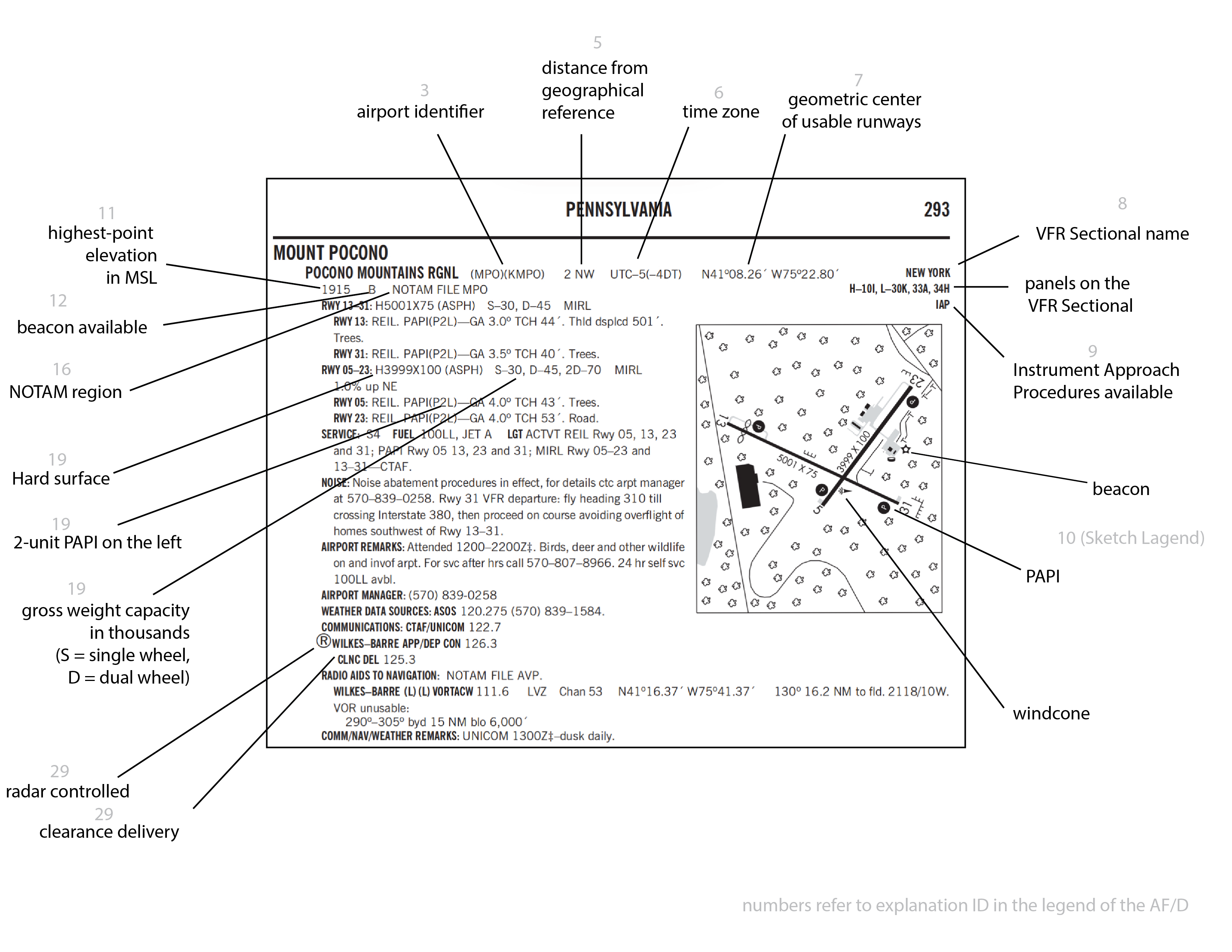 Figure: A/FD legend
-
VFR Sectional
- Symbols
- Airport
- Airspace
- Class B: blue solid, complex inverted wedding cake
- Class C: magenta solid, 2-layer inverted wedding cake
- TRSA (Terminal Radar Service Area): gray solid, 2-layer inverted wedding cake
- Class D: blue dashed circle
- Class E to surface: magenta dashed circle
- Class E to 700ft: faded side of magenta band
- Class E to 1200ft: solid side of magenta band
- Airport color code
- blue: towered
- can lie in airspace Class B to Class E (e.g., KFNL is towered, but in Class E)
- magenta: untowered
- airport color is not tied to airspace color
- symbols enhancements
- pins/cross: fuel available
- star: airport beacon in use
- flags: used as VFR visual checkpoint to identify position for initial approach callup
- Airport string
- top line optional: NO SVFR (i.e., no fixed-wing airplan special VFR)
- first number is elevation
- Radio aids to navigation
- VOR: hexagon (something that emantes in many directions)
- DME: box around the hexagon
- VORTAC: TAC ~ TA ~ TriAngular; triangular VOR symbol
- Symbols
-
Geodetic coordinate system uses
- latitude and longitude
- latitude (zero lÄtitude goes through the Äquator)
- longitude (zero LONgitude goes through LONdon)
- formats
- deg °, min ', seconds "" W/E or N/S
- e.g., 76° 01' W, 36° 24' N
- VFR Sectional
- annotation is algined with the respective line
- properties
- lines of latitude are parallel to the equator and each other and have constant distance.
- 1 minute of latitude = 1 nautical mile, i.e., 1 degree of latitude = 60 NM = 60 minutes
- lines of longitude cross the equator at right angles
- The meridian (= 0° lines of longitude) passes through Greenwich, England.
- meridians are with respect to true north
- latitude and longitude
-
NOTAMS (notice to airmen/air mission)
- contain time-critical information
- types
- NOTAM-D (domestic)
- runway closures
- VASI outages
- runway condition and status information
- taxiway closures
- FDC NOTAM (flight data center)
- changes to charts, procedures, airspace usages, e.g.,
- TFRs
- SAA NOTAM (special activity airspace)
-
VFR radar service
- Sequencing to the primarry Class C airport
- 500 ft of vertical separation or visual separation (3-2-4-e) [CAN BE 500!]
- traffic adivsories
- conflict resolution
- safety alerts
-
IFR standard separation
- 3 NM laterarally within 40 niles of the radar site
- 5 NM beyond 50 miles of the radar site
-
VORs
- shows magnetic north
- ~ 10 NM in radius (but not formally fixed)
K1a: Use of an electronic flight bag (EFB), if used
K2: Altitude selection accounting for terrain and obstacles, glide distance of airplane, VFR cruising altitude and effects of wind
-
altitude selection based on
- terrain and obstacle clearance
- airspace
- hemispherical alitiude rule for VFR cruise (NEODD/SWEVEN) and +500 VFR offset
- based on magnetic course, i.e.,
- based on magnetic, not true north
- based on course, not heading
- based on magnetic course, i.e.,
- glide distance to closest airports
-
wind triangle:
- reading a given wind trianngle:
- first check on which line the airplane is travelling
- triangle sides
- C to B: true course (or ground track after flying a course), ground speed
- C to A: wind speed, wind direction
- A to B: true airspeed, true heading
- reading a given wind trianngle:
-
Cross-wind and tailwind/headwind components
- input:
- windspeed V_w
- relative angle \theta
- output:
- longitudinal compoment:
- V_w * cos(\theta)
- crosswind component:
- V_w * sin(\theta)
- mnemonic:
- cross-wind sounds like crosssin, so use sin
- longitudinal compoment:
- input:
-
wind correction
- due to the clockwise annotation of the compass rose, wind correction angles can be interpreted as a number line
- from left (negative) to right (positive)
- negative wind correction angles are winds from the left and require steering to the left
- positive wind correction angles are winds from the right and require steering to the right
-
glide distance rules
- at 10'000 feet, assuming C172 glide ratio, you can glide 90'000 feet / 5500 feet/NM ~ 15 NM -> multiply altitude in feet / 1000 with 1.5 to obtain glide ratio in NM
- glide ratio 9:1 equates to a slide slope of approx. 6 degrees
K3a: Calculating time, climb, descent rates, courses, distance, heading, true airspeed, and groundspeed
-
Converting true course/heading to magnetic course/heading
- The geometric northpole is offset from the magnetic north pole by approx. 400 to 800 km.
- It wobbles by 80 km daily and shifts by approx. 80 km annually (thus requiring runway markings to be updated regularly).
- The compass needle points to magnetic north rather than true north.
- This results in a difference, called magnetic variation (= magnetic declination).
- This is independent from compass error (= magnetic deviation), caused by magnetic fields local to an aircraft.
- Magnetic variation
- is maximal at 180° on the line between true and magnetic north pole (we could calle this the antagonic line).
- is 0° on the extensions of this line, called the agonic line.
- Isogonic lines are lines of equal magnetic variation, and show either westerly or easterly variation, annotated as such on the VFR sectional (magneta dashed lines).
- true course/heading PLUS westerly variation = magnetic course/heading
- true course/heading MINUS easterly variation = magnetic course/heading
- mnemonic: east is least, west is best
-
Converting indicated to true airspeed
- Airspeeds
- Indicated airspeed
- pressure differential between static and dynamic port, therefore measure of lift
- Calibrated airspeed
- indicated airpseed corrected for instrument error
- look up calibrated airspeed from indicated airspeed
- True airspeed
- Calibrated airspeed corrected for altitude and non-standard temperature
- correcting for pressure by multiplying IAS with \sqrt{\rho_{msl}/\rho}
- correcting for temperature by multiplying IAS with \sqrt{\T/\T_{MSL}}
- approximation:
- 2% per 1000 feet of pressure altitude
- Flight Computer
- computing TAS at Top of Climb
- enter OAT (outside air temperature) from weather data
- enter pressure altitude
- compute pressure alitude with flight computer
- enter indicated altitude (IAlt) from desired altitude
- enter barometric pressure from forecast (use current METAR altimeter setting as usually no forecast is available)
- enter pressure altitude from computation
- hit compute and read TAS
- Indicated airspeed
- Airspeeds
K3b: Calculating estimated time of arrival, including conversion to UTC
- Time zones
- UTC = GMT
- in Britain
- Greenwich Mean Time (GMT) in Winter [UTC+0]
- British Summer Time (BST) in Summer [UTC+1]
- in Germany
- Central European Time CET in Winter [UTC+1]
- CEST in Summer [UTC+2]
- in the US
- nomenclature
- Standard in winter
- Daylight Saving Time (DST) in summer
- zones in the US
- ET (Eastern Time)
- EST = Eastern Standard Time [UTC-5]
- EDT = Eastern Daylight Time [UTC-4]
- CT (Central Time)
- CST = Central Standard Time [UTC-6]
- CDT = Central Daylight Time [UTC-5]
- MT (Mountain Time)
- MST = Mountain Standard Time [UTC-7]
- MDT = Mountain Daylight Time [UTC-6]
- PT (Pacific Time)
- PST = Pacific Standard Time [UTC-8]
- PDT = Pacific Daylight Time [UTC-7]
- can be foun in figure 27 (Time Conversion Table)
- example
- Departure time: 0945 EDT = 1345 UTC
- Flight: 2h
- Landing: 1545 UTC
K3c: Calculating fuel requirements, including reserve
- fuel requirements
- at day: enough to fly to first point of intended landing plus 30 minutes at normal cruising speed
- at night: enough to fly to first point of intended landing plus 45 minutes at normal cruising speed
K4: Elements of a VFR flight plan
- 3 Message Type
- 7 Aircraft Idnetification
- 8 Flight rules
- Type of Flight
- 9 Number
- Typer of Aircraft
- Wake Turbuluence Category
- 10 Equipment
- 13 Departure Aerodrome
- TIme
- 15
- Cruising Speed
- Level
-
- VFR Cruising Altitude (defined as the planned altitude for the first part of the route)
-
- Route
- Total EET (Estimated En-Route Time)
- 16 Destination Aerodrome
- ALTN Aerodrome
- 2n Altn Aerodrome
- 18 Other Information
- 19 Endurance
- Persons on Board
K5 Procedures for filing, activating, and closing a VFR flight plan
K6: Inflight intercept procedures
-
https://www.faa.gov/sites/faa.gov/files/2022-01/Intercept-Procedures.pdf
-
Signals by the fighter
- "Company" (fighter left of the cockpit matching speed and heading): You have been intercepted.
- Slow level turn: Follow me.
- Abrupt turn across nose, potentially dispensing flares: Turn now in direction of fighter.
- Circling airport, lowering landing gear, overflying runway in direction of landing: Land at this airport.
- Breakaway maneuver